The rear suspension was rebuilt 10 years ago during the frame-off restoration of my 1972 TR6. At that time, original equipment rubber bushings from The Roadster Factory were installed, the lever shocks were replaced with a Moss Motors (P/N 670-118) tube shock conversion kit, and a pair of new old stock Triumph rear springs, discovered at going out of business sale at a local foreign car parts store, were installed in place of the rusted originals.
Now, ten years later, I decided to go through the suspension and replace the rubber bushings with a new set of polyurethane bushings from Moss Motors (PN: 681-255), replace the factory rear springs with a set of Triumph Tune TT4212 springs (to match the front set of TT 4001 springs), and replace the factory trailing arm mounting brackets with Goodparts adjustable training arm brackets and uprated hardware purchased from Wishbone Classics.
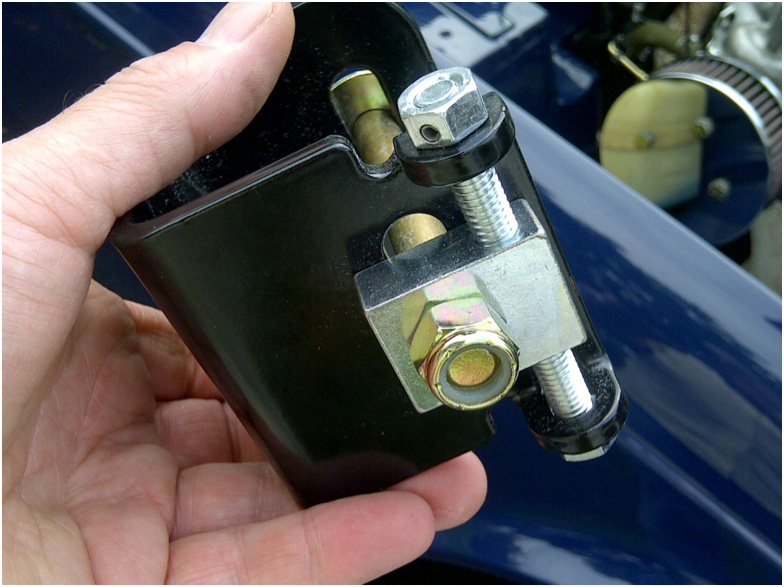
Goodparts adjustable trailing arm brackets
The Goodparts adjustable trailing arm brackets, Figure 1, are a solid improvement over the factory part allowing easy adjustment of the rear wheel camber. Fitted with new hardware, the Richard Good brackets are definitely eye-candy with a practical purpose.
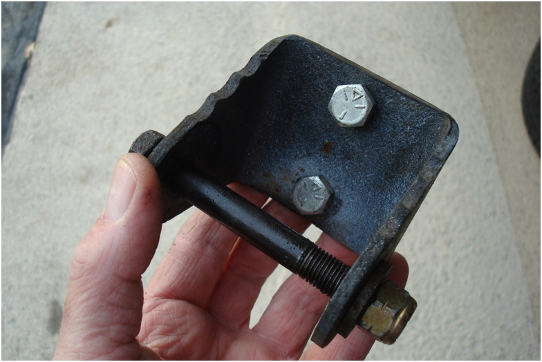
Original TR6 trailing arm
The original trailing arm used a combination of brackets, Figure 2, in various configurations to adjust the rear wheel camber. An excellent article describing adjustment using the factory brackets can be found on the Buckeye Triumphs Website.
Once all the new parts were collected I began with the teardown, beginning on the passenger side. Many of our members have completed these upgrades on their cars, so I won’t revisit specifics, but rather describe my experience and provide additional information for the members that are considering installing these products,
Disassembly
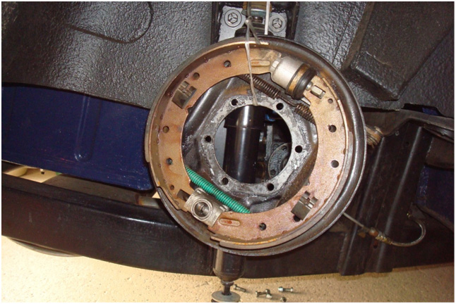
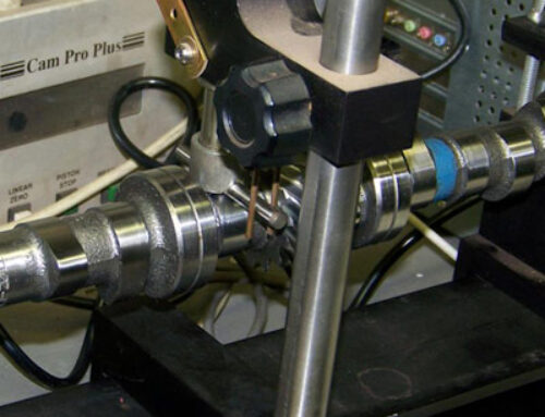
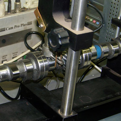
Disassembly of the rear trailing arms include removing the wheel, unbolting the parking brake cable and brake line, Figure 3, which are secured to the trailing arm, the drive shafts, and the brake backplate. Detailed instructions are available in the Bentley or Haynes Manuals.

Dis-assembly of the rear trailing arms
Once the hub assembly and drive axle were removed I was able to lift the brake backplate up and off the trailing arm, Figure 4, and tied it up out of the way.
Moving brake backplate up and off the trailing arm
Removing the rear spring involves supporting the trailing arm with a floor jack, so the shock can be undone and the trailing arm slowly lowered until the spring can be removed. Once the spring and shock were removed, the trailing arm was left hanging free, attached to the frame by the factory brackets. Four bolts on each side, (2 per bracket), secure the factory training arm brackets to the frame. After unbolting, I pulled the entire trailing arm with brackets still attached from the car.
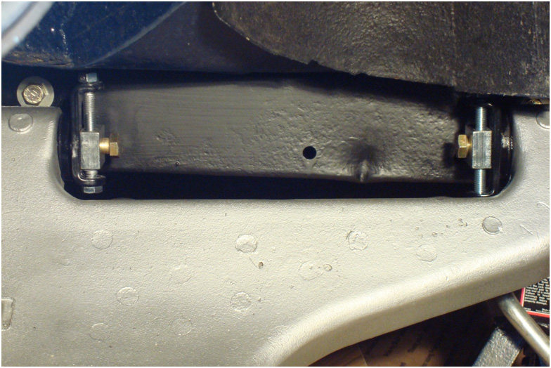
It is important to note that shims are installed behind each bracket. These shims are used to set the toe-in setting of the rear wheel during an alignment. I took care to count these installed shims so they could be reinstalled back behind the new trailing arm brackets at the same location using the same number of shims where the original bracket was located, Figure 5.
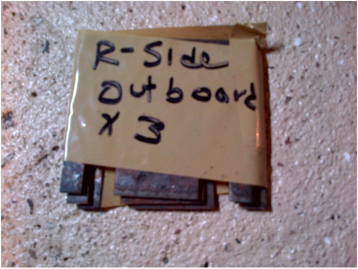
Noting number of shims for reassembly
Repair of U-Joint
After removing and inspecting the u-joints on the driveshaft, I discovered that one of the u-joints had a grease Zerk fitting broken off and repair was necessary, Figures 6, 7, and 8.
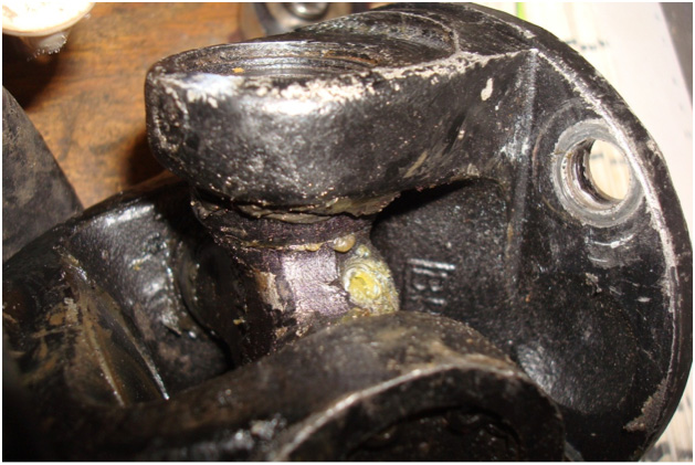
U-Joint missing grease fitting
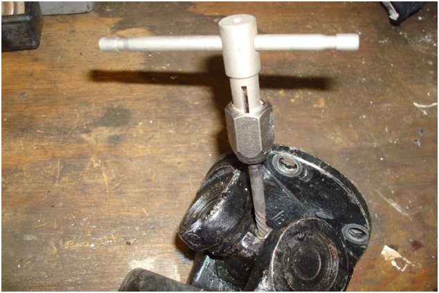
U-joint repair
A #2 screw extractor was gently tapped into the remains of the damaged Zerk fitting. By turning the screw extractor counter clockwise, the spiral threads of the extractor bit into the remaining threaded connection in the damaged fitting, backing it out.
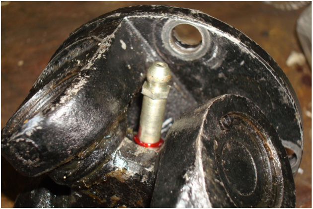
Backing out damaged fitting
Bushings
Although I am not overly fond of too much polyurethane, and considering my preference for factory rubber in the suspension, I had to compromise this time because of my desire to improve the road handling of the car. Since the trailing arm movement can compress polyurethane less than rubber, I hoped to achieve -a more sure footed feel-without being overly stiff while driving. Although I was still a bit melancholy about the bushing upgrade, I embarked on the project.
Removal of the factory rubber bushings can be difficult; however, I used the technique described by Leonard Renkenberger in the Six-Tech Manuals, drilling half-dozen holes through the rubber bushings with a 9/32” drill bit. Then, positioning a 3/4in brass drift against the metal sleeve in the rubber bushing, the bushings were driven out with two or three blows from a 5 lbs. sledge hammer. [You can find these instructions and more on BobbyD75TR6’s website at http://tr6.danielsonfamily.org/Files/6-Tech-PDFs/Rear-Suspension.pdf. ]
Surprisingly, the rubber bushings that I was replacing were in excellent condition. Even after 10 years the rubber was still pliable, and without deformation or deterioration.
Before installing the new polyurethane replacements, Figure 9, I painted the trailing arm with a coat of Dupli-Color Cast Aluminum Ceramic Paint. The new bushings were then pressed in easily and I was now ready to reinstall the trailing arms to the frame.
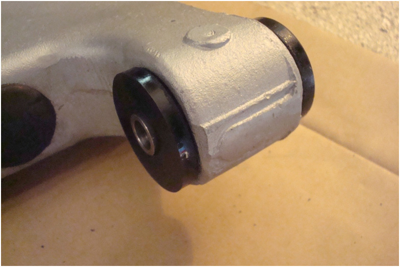
Installing new polyurethane bushings
Reinstallation
The brackets included instructions enclosed with the parts, and although I read the instructions several times I was not confident that I was installing them the best way possible. I contacted Richard Good of Goodparts for clarification and a recommendation on how to best install the pivot bolts. The original pivot bolts were installed with the head of the bolt on the inboard bracket facing the frame rail and the head of the bolt on outboard bracket facing in towards the center of the car. This apparently was done to facilitate removal of the trailing arm, allowing the outboard bolt to be removed, leaving the bracket attached to the frame and the inboard bracket removed with the trailing arm. After our conversation, I chose to place both bolt heads toward each other so the trailing arm can be removed, leaving both brackets still bolted to the frame, Figure 10.
Trailing arm assembly
The remaining reassembly, which is the reverse of the disassembly, can now be completed. The new Triumph-Tune Spring, Figure 11 was installed, the shock reattached, Figure 12, the brake backplate fitted and the drive axle slipped back in. I used new nyloc nuts on the hubs and drive shafts, Figures 13 and 14, carefully torqueing each one to the recommended specifications. (A close look at Figure’s 11 and 12 will show that I have also completed the Rick Patton TA repairs.)
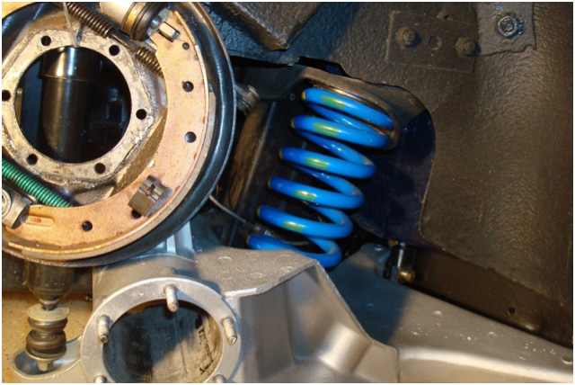
Reassembly with Triumph-Tune spring
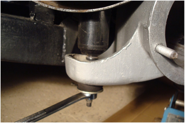
fig12
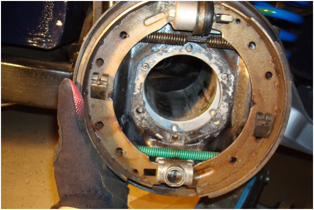
fig13
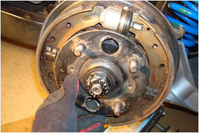
fig14
Speed-Bleeders
Finally I installed a set of Speed-Bleeders to simplify bleeding the brake system, Figures 15 and 16. These were provided by a friend and local 6-Pack member BobbyD75TR6. Installation is simple, using the proper sized wrench remove the originals and install the replacements. With the Speed-Bleeders, it was easy to crack open the bleeder ¼ to ½ a turn and pump the brakes. Because there was no need to close the bleeder between brake pumps, this was easily a one person job.
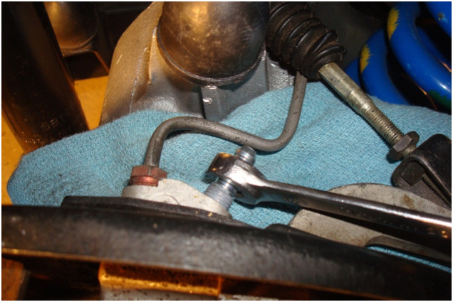
fig15
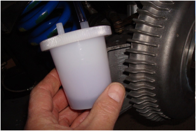
fig16
Camber Adjustments
After the brackets were installed, both rear wheels showed an excessive negative camber with the bottom of the wheels being farther out than the top. The recommended factory camber for the TR6 is +1 degrees to –1/4 degrees of camber. Following the instructions detailed on the Buckeye Site, I used a carpenters framing square and metal ruler to obtain the current measurements and plugged them into a Microsoft Excel spreadsheet I created, Table 1, with the formula described in the Buckeye technical article, [Camber Angle = (57.3 degrees) X (difference between top& bottom)/ (diameter)], to obtain a starting point so I could begin the adjustments.
Camber adjustments on the Goodparts brackets are made by turning the adjusting bolts which in turn raise or lower the fulcrum bolt, changing the camber. Raising the car back up on the jack, I ensured that the fulcrum bolts were loosened and made 8 full counterclockwise turns to the adjusting bolt on the inner bracket on the left-side, and 9 full counterclockwise turns to the adjusting bolt on the inner bracket on the right-side. Dropping the car back down off the jack, I pushed it back and forward in the garage to settle the suspension, and then rechecked the measurements. It was necessary to repeat the previous steps a few times and make minor adjustments to the outer bracket adjusting bolts to complete the camber adjustments.
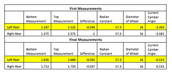
Camber Adjustments
Conclusion
Taking a short jaunt around the neighborhood I was relieved that the additional polyurethane in the rear suspension did not result in a jarring ride. The combination of the matched springs, new bushings and shocks seemed balanced and the car was firmly planted to the road through the corners. Sadly now the winter months will curtail my driving so a long-term evaluation of the upgrades will not be available until spring.
