By Ivan Bailey
Well I finally braved the cool temperature in the garage to begin my winter project, swapping out the current camshaft for a new one to take better advantage of the bench-flowed and ported head. If you have been following my progress with the engine performance improvements of my 1972 TR6, published in the spring and summer 2011 Issues of 6-PACK, I took a break from the engine upgrades and spent time renewing the rear suspension-projects which were detailed in the winter 2012 issue. Now that my driving season is over, I returned my attention back to the engine upgrades.
The current camshaft, a Kent TH2-6, provides a limited 0.381 gross valve lift[1] choking the flow to the head at roughly 4700RPM on the intake and 5300RPM on the exhaust. Although with this camshaft, the engine performs with 131 ft. /lbs. of torque@3200 rpm and 107 horsepower@4800 rpm (nearly twice what a stock TR6 provides), the engine demands more flow from the intake valve and simply cannot draw it through the limited valve opening; the only solution is a camshaft replacement.
1 Gross valve lift – measured before the hot lash – is used in the article for consistency.
2 Duration is when both the intake and exhaust valve are open at the same time.
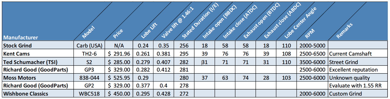
With this in mind, I began researching camshafts. I specifically looked for cams that have a shorter duration[2] than my current camshaft and more valve lift. The intent was to pick up additional bottom end power and improve the flow at higher RPM. See Appendix A Camshaft Comparisons. I have been told that with my current engine preparation, I could easily run above 6300-6500 RPM, and it has been suggested that a minimum of 0.486″ intake valve lift and 0.429″ exhaust valve lift would be necessary to obtain peak performance at that RPM. However, I am looking for a useful increase in power without having to spin the engine above 5,000-6000 RPM constantly.
Narrowing the choice to four, from the dozens of cams available, I plugged each camshafts specification into my Engine Analyzer Pro Simulation Software to compare the performance differences of each.
Simulation Runs resulted in the following:
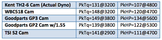
Two camshafts clearly met my requirements: the WBC518 from Wishbone Classics and the Goodparts GP3[3]. I believed that the horsepower, torque, and RPM figures for either of these cams were more than adequate.
3 The additional cost of the GP2 with 1.55 roller rockers priced it out of the competition. The S2 camshaft offered a nice improvement in lift, at an affordable price. However, I was looking for less duration than it provided, leaving me with the remaining two camshafts.
It is important to check that any new camshaft would not cause the valve springs to coil bind. Coil bind is when the valve spring is fully compressed to the point that all the coils are tight up against each other. This condition, described by Ken Dolhonde AKA Poolboy in his 6-pack Topic titled “Cams and Complications,” resulted in valve train failure. At full lift, I was cautioned that at least 0.075” distance between the spring coils is recommended. Therefore, during the head milling operation, described in detail later, I checked the intake and exhaust spring installed heights. The springs were placed in a tester, and compressed to their installed height and measured. Heights of 1.375” on the exhaust and 1.400” on the intake were confirmed. The springs were then further compressed to the maximum valve lift using the cam specifications from Wishbone and Goodparts. It was concluded that both camshafts offered in excess of 0.0810” between the spring coils. Either camshaft would pose no issue with spring coil bind during normal operation, (assuming stock rockers and the recommend valve lash), the WBC518 with 0.295 of cam lift or 0.428 gross valve lift and the GP3 with 0.282 of cam lift or 0.395 on the intake/0.393 on the exhaust.
After much research and e-mail discussions with the vendors, I selected the custom ground WBC518 camshaft. The WBC518 is ground on a new camshaft blank, which allows a higher lift profile and offers the shorter duration that I was looking for. (Thanks to Richard Good and Kai Radicke who were generous with the information and advice, they provided). With the camshaft selected, it was time to move from the books and computers to the wrenches and rags.
Replacing the camshaft required that the head be removed to get access to the lifters. Once the lifters were out the camshaft can be slide out from the engine through the grille opening. The steps I followed to install the new camshaft were confirming the current installation, removal and replacement of the current camshaft, degreeing the new camshaft, adjusting the valve lash, and breaking in the new camshaft.
Removing the hood allowed easier access to the engine bay. Fortunately, my son and a friend stopped by that afternoon for lunch, and they volunteered to help me remove the hood. It was unbolted, taken off and stored away from the garage. Next, the radiator assembly, intake manifold, hoses, and fuel lines were removed quickly and easily. The exhaust manifold was unbolted from the head but left in place in the engine bay, Figure 1. It was necessary to remove a few head bolts from the block, and then with a sharp tug on the front of the head, I was able to lift the head from the engine with ease. Sliding the newly rebuilt harmonic balancer off the front of the crankshaft proved more difficult. Although it was simply a press fit when installed, the harmonic balancer did not want to budge when trying to remove it. With some persuasion using a pry bar and (patience as well) I was eventually able to remove it. I stored small parts and fasteners in labeled plastic zip bags, as they were unbolted and removed. Keeping them labeled and separated facilitated the rebuild, as did the use of a digital camera to document how everything came apart.
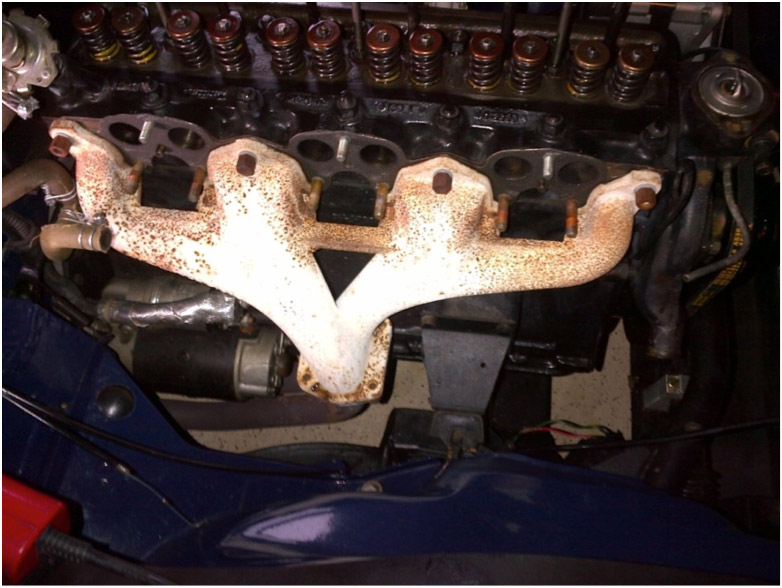
Engine Disassembled for Cam Installation
Confirm the Current Installation
The Kent camshaft should have been installed 108 degrees ATDC (After Top Dead Center). I wanted to confirm this. Having this documented will allow me to reinstall the original Kent camshaft (if necessary) or reassemble the engine using a camshaft ground with the same lobe center angle easily and in the same location with intake lobe number one at full lift.
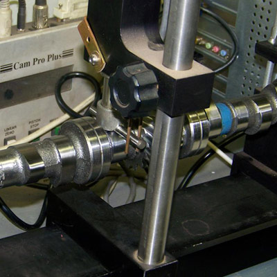
Before I could proceed, I needed to establish TDC (Top Dead Center). The technique to find TDC has been extensively covered in two excellent 6-Pack articles ,“How to Upgrade and Calibrate your TR6 Camshaft” written by Michael Williams in the 2007 Issue Number Three and “Understanding Cam Timing,” written by Jeff Belanger-AKA Morphe in the Spring 2011 Issue of the magazine. Sufficient to that to say that I used a piston stop installed across the top of cylinder one, Figure 2, and a degree wheel bolted to the front of the crankshaft, Figure 3, to locate TDC.
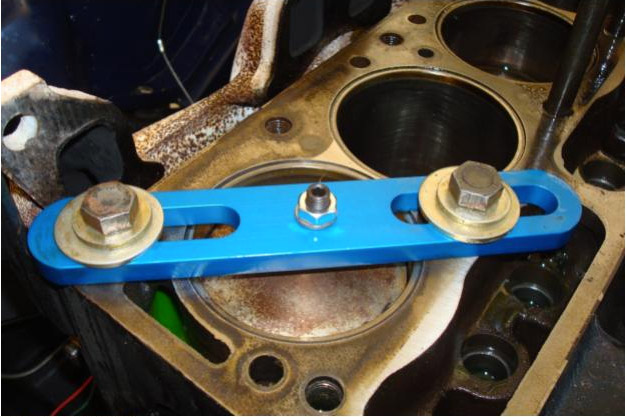
Figure 2 Piston stop installed
Knowing TDC, I was now able to measure the current camshaft’s specification from the lifter using a dial indicator, (sometimes called a drop indicator). I securely mounted the dial indicator to the head with its pointer seated firmly on the lifter at the number one intake; I rotated the crankshaft a number of times to confirm that full lift was at 108 degrees ATDC.
Leaving the crankshaft and camshaft in their position, I placed a straight edge across the center of the cam gear and through the center of the crank gear and made two center punch marks along that line, one on each gear (4) Illustrated in the Bentley Triumph 250 and TR6 Manual as operation 12.41.05 Sheet 6. With this task completed, I focused my attention on installing the new camshaft-which will be degreed in using the specifications from the camshaft grinder.
(4) I used new OE style cam and crank gears during the original rebuild, and unlike the original factory gears; the new products did not have factory markings
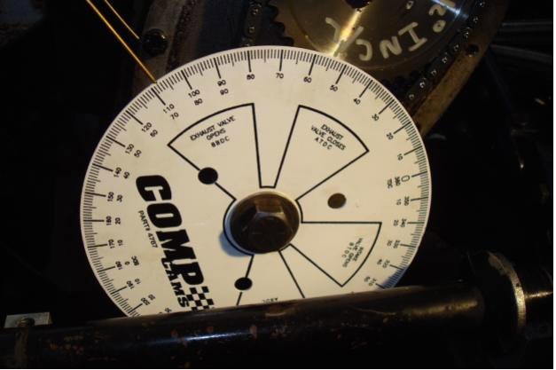
Figure 3 Degree wheel installed
Removal of the Current Camshaft and Installation of the New Camshaft
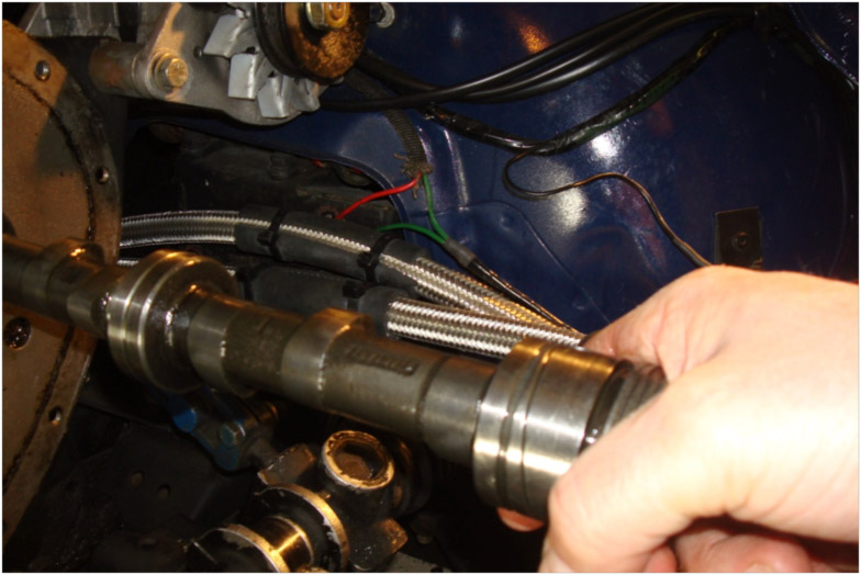
The lifters, fuel pump, distributor, cam gear, chain, and cam locating plate were unbolted and removed. I then removed the two bolts from the driver-side motor mount and jacked-up the engine a few inches. The camshaft then slide easily from the engine block, through the grille opening, Figure 4.
While waiting for the new camshaft from Wishbone Classics to arrive, I further disassembled the head, removing the valves, and springs, and dropped it off at PMR Racing in Newington, Connecticut. After running it through a spray wash cabinet to remove any carbon build up in the chambers and ports, the head was cut down to a thickness of 3.416 to increase compression (During the original rebuild, the head was originally cut down from 3.55 to 3.440). With this head thickness, I expect to increase the CR to a solid 9.6. This change in the head width requires that my tubular pushrods, which had been trimmed to accommodate the previous thickness of the head, might need to be cut again. Rather than guessing at the length needed, Kai of Wishbone Classics offered me an adjustable pushrod to use. Once the head and rockers are in place, I will install the adjustable pushrod and adjust the length until it produces the valve geometry I want. Then simply lock the locknut in place, remove it, measure it, and get the pushrods made to the exact length. While the headwork was being completed, I shipped off my pushrods to Kai and waited for the camshaft and the adjustable pushrod to be delivered.
Two days later, I received a phone call from Phil, the owner of PMR Performance, letting me know that my head was completed and the chambers cc’d. The newly milled head, with the valves seated, had a volume of 45cc. Consulting the chart at http://www.goodparts.com/tech_docs/TR6_Compression_Ratio.html[1] this new volume should provide, with the blocked deck and the .30 thousandths overbore, a compression ratio of 9.67 to one.
Finally, the new camshaft and lifters arrived. The parts are truly a work of art. The quality of the lifters and camshaft, especially with regard to the surface finish was outstanding. In conversations with Kai of Wishbone Classics, he had expressed how he is personally very meticulous about surface finishes. A finer finish provides a far more long-lived part and lowers operating friction[2]. By eliminating the microscopic crevices that normally exist on regular cams and lifters, the oil film is much more even and stable between the cam and lifter face. “Better surface finishes also reduce the amount of break-in that takes place, because you don’t have to wear down those peaks to meet the valleys on the surface of the part – because they were removed during manufacturing.” Kai Radicke, Wishbone Classics “No oil in the world can make up for poorly manufactured or finished components.” Now that all the pieces have arrived, it is time to install the camshaft.
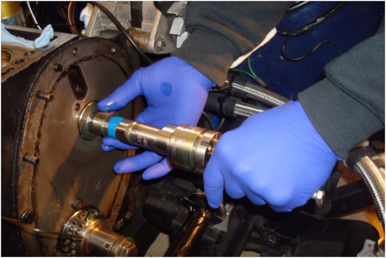
Luckily, I was able to get in touch with Al Gary aka Trick 6 of the 6-Pack forum, and he offered his services to help me in installing and degreeing the new camshaft. This would be my first camshaft installation and I was glad that a skilled and knowledgeable Six Packer would be able to work with me. We made our plan to meet the following morning and I could not wait to get this project buttoned up. Al arrived the next morning with his piston stop and torque wrenches, and after a quick cup of coffee, we began. Installation of the camshaft went without incident. Degreeing the camshaft, however, was not as easy as I had prepared for. Al first covered the lifter bank with towels to protect anything from falling into the engine. The engine was then lifted a few inches to allow the camshaft to pass through the grille opening; Al then carefully guided the new camshaft into the block Figure 5, and secured it with a new cam locating plate.
New cam installed
Originally, I planned to repeat the technique I used to confirm the original installation, using the new timing marks. This however proved to be almost impossible as none of the timing marks would align. After a quick phone conversation with Kai at Wishbone Classics, we decided to install the cam using the full intake lift method using a dial indicator to check the cam movements, Figure 6. From TDC we rotated the crankshaft to 108 ATDC degrees, confirmed that the camshaft was installed with full intake lift at that location, then checked that full exhaust lift was in accordance with the camshaft specification. We then positioned the cam gear and chain in place.
Confident that our dry run was correct we disassembled everything and began again; determined TDC, set up the crankshaft and camshaft, installed the cam gear, chain, and discovered that during our reassembly we were off a tooth on the crank gear. We are not sure how this happened, but measure twice and cut once is the theme. Finally, on our third run as on the first, everything was dead on. We then confirmed the installation by checking both intake and exhaust valve lift relative to crank degree as per the cam specifications.
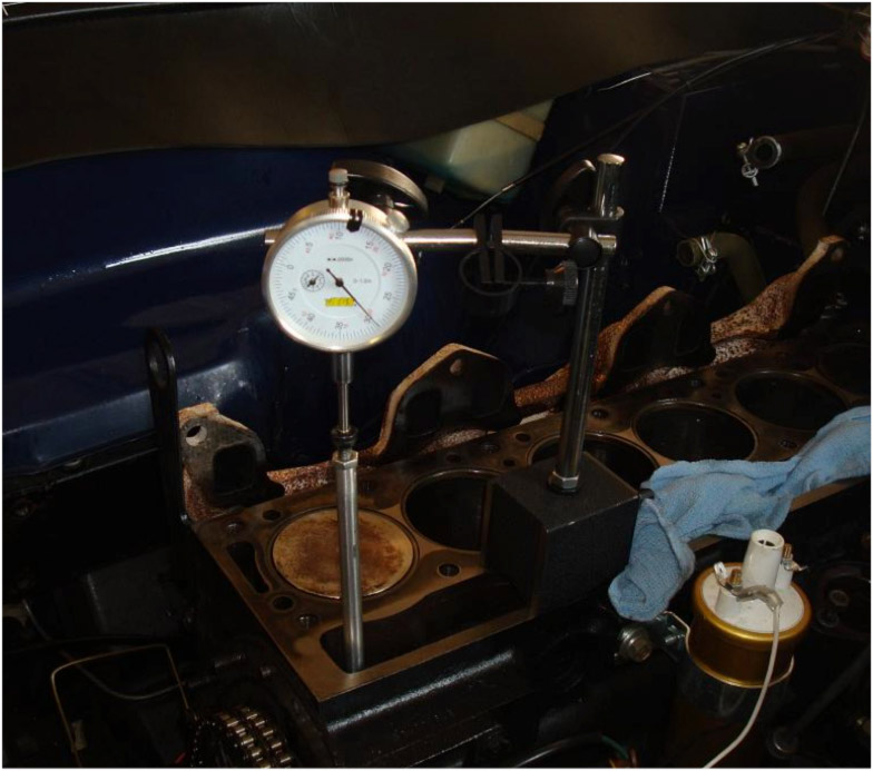
Figure 6 Verifying the installation by observing cam events (exhaust displayed)
Satisfied we had performed a good day’s work Al departed for home with a smile on his face.
The following day I used a bottoming tap to chase the threads in the block in preparation for final assembly, and cleaned the head gasket mating surfaces on the head and the block by wiping them down with brake cleaner. Now it was time for me to reassemble the rest of the engine with new gaskets, new lifters, and fresh ARP head bolts.
With everything assembled, I used the adjustable pushrod, Figure 7, to determine the new length for the pushrods, following the steps described in Appendix B.
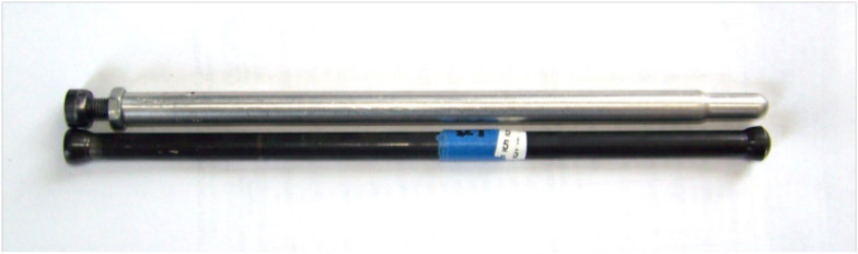
Figure 7 Adjustable pushrod and original tubular pushrod. Photograph courtesy of Wishbone Classics.
The new measurement was sent to Wishbone, who already had my original tubular pushrods. Surprisingly, we discovered that the pushrods had been cut short during the original engine rebuild, and may have to be eventually replaced with new –longer- proper length pushrods, so the adjustable pushrods were returned and once received, I wasted no time installing the original pushrods.
Adjusting the valve lash
The final check before starting the engine with the new camshaft was to adjust the valve lash and recheck the rocker geometry. The ideal rocker geometry is determined by the position of the rocker tip on the valve stem. While the valve is closed the rocker tip is slightly behind the center of the valve tip and when the valve is ½ open, the rocker tip is slightly ahead of center of the valve tip, and at full lift, the rocker tip, Figure 8 is slightly behind the center of the valve tip.
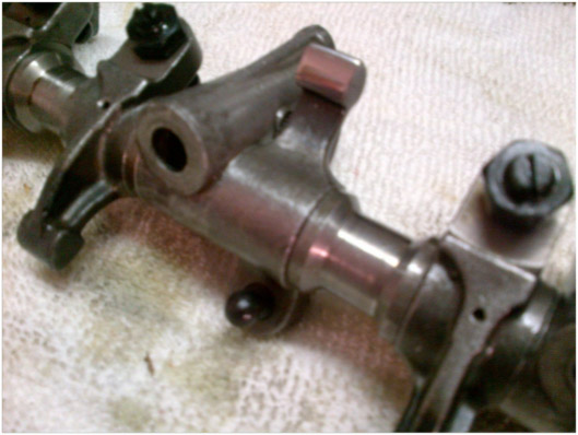
Figure 8 Rocker tip
Using a technique taught to me by my father, I marked the top of an intake and exhaust valve stem with black marker, Figure 9, then installed the rocker assembly, and set the cold valve lash, Figure 10.
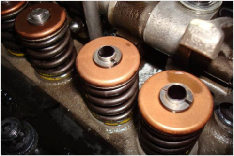
Figure 9 Marked stems.
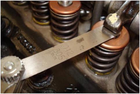
Figure 10 Checking the valve lash
After spinning the crank a few revolutions, Figures 11 and 12, I disassembled the valve train and inspected the rocker tips and valve ends to see where the black markings were transferred onto the rocker arms. This provided me with a visual clue to where the contact area is located, Figures 13, and 14.
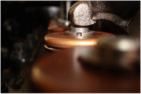
Figure 11 Intake rocker tip in the closed position.
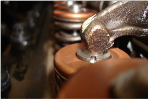
Figure 12 Intake rocker tip position full-lift
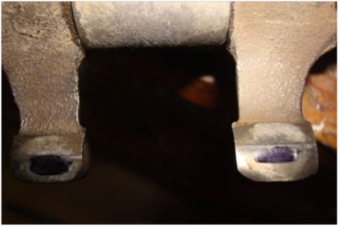
Figure 13 Wipe mark rocker tips
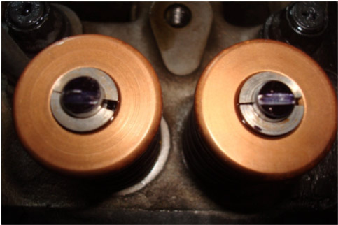
Figure 14 Contact area on valve tips.
Satisfied that the valve geometry was a best as I could get it, it was time to move on to finish the project.
Breaking in the new camshaft
Before startup, I primed the oil system by using an electric drill set-to reverse and a tool made from a steel rod with a slot cut into the end. I then double-checked the ignition and started the engine, allowing it to run at 2300 rpm for 20 minutes without stopping. Once the break-in was complete, I checked the valve lash again and made a few minor adjustments. Finally, I changed the oil using 5 quarts of Brad Penn Oil from TS Imported Automotive and a new Purolator PureONE oil filter.
Conclusion
With the new camshaft, I am hoping to finally reap the benefit of the reworked intake manifold and the ported head. Debaise Bros. Custom Cycles and Hotrods in Meriden CT were contacted to perform the Dyno session. I was anxious to find out if the early simulation figures would pan out. With the engine buttoned up and ready to go, Figure 15, I am off to the Dyno tune session.
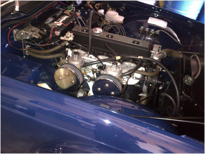
Figure 15 Buttoned up and ready to roll.
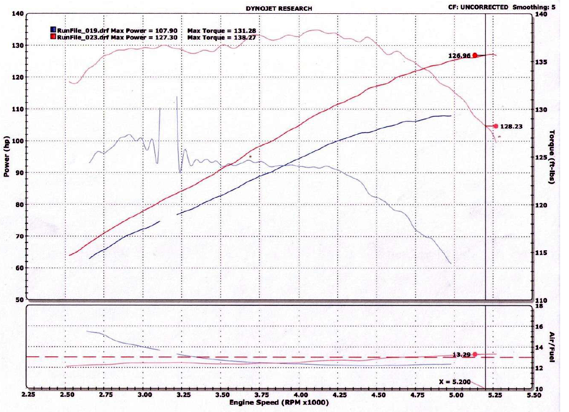
The first Dyno run of the day resulted in numbers of 119.54 rwhp and 143.67 of torque. Three more runs delivered consistent hp and torque figures of 128 rwhp and 139 of torque. The final run resulted in 127.30 rwhp at 5200 RPM and 138.27 of max torque at 4100 RPM, Appendix B Dyno Results. Unlike previous sessions at Debaise, no additional tuning was performed during these Dyno runs. The best run we had with the Kent camshaft achieved horsepower and torque figures of 107 rwhp and 131.28 ft. /lbs. of max torque and an almost perfect .air/fuel ratio (AFR) of 12.32:1.
The new WBC 518 camshaft and the minor compression increase provided more than 20 additional HP and 7 ft. /lbs. of torque, when compared to the best Kent Dyno run. However, in tuning the engine, I try to keep the AFR in between 12.5:1: and 12.75:1 to maximize performance. Therefore, additional tuning to obtain the optimum AFR[5] is necessary.
(5) In evaluating the current results, I noticed that the (AFR) mixture is a little high at 13.29:1.
Kai at Wishbone Classics knows I like to document and publish my TR6 improvements. He offered to digitally profile and graph a comparison between the TH2-6 and the WBC518.
The graph at Figure 17 below, illustrates the difference between the long duration, low lift design of my original Kent camshaft, a profile popular 15+ years ago, and the tighter duration, higher lift camshaft profiles manufactured by Wishbone Classics today. Overall, the Kent is an older design and not one suited for the street. By adding duration to overcome the velocity limitation, the overlap between the intake and exhaust is larger than the overlap of the three other profiles illustrated.
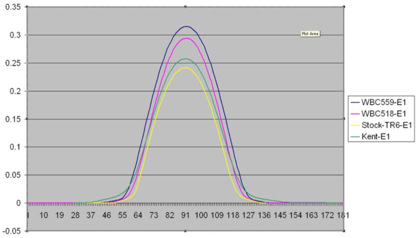
Figure 17 Comparison of Cam lift degree
The chart shows the camshaft lift per degree of camshaft motion for four different profiles, a stock late TR6 cam, the Kent TH26, the WBC518 (street performance profile) and WBC559 (hillclimb rally profile) camshafts. The overlap of the Kent reduces low-end engine torque, increases emissions, and decreases fuel economy. In other words, an engine operating in lower RPM (3000 and below) will be operating very inefficiently with the Kent profile. The Kent however sang beautifully, and at RPM above 6000, the sound of the engine was music!
The other profiles, including the stock TR6 profile, have greater velocity per degree of cam lift. A major benefit of my new WBC camshaft is that the cam lift is maximized, in order to maximize cylinder filling. This increases low-end torque and drivability, preserving emissions and fuel economy characteristics.
With this engine modification completed, and a new baseline established for future tuning I am pleased that the time and money spent on this upgrade was worth the performance gain. Driving the car is a blast and I have to consciously let up on the accelerator so the engine does not rev beyond my self-imposed 5000-RPM limit as the engine wants to continue revving. Next, I hope to tweak the AFR and install the header I have had stored in my workshop for the last two years. Stay tuned!
Appendix A – Camshaft Comparison
Appendix B – Dyno Results
